
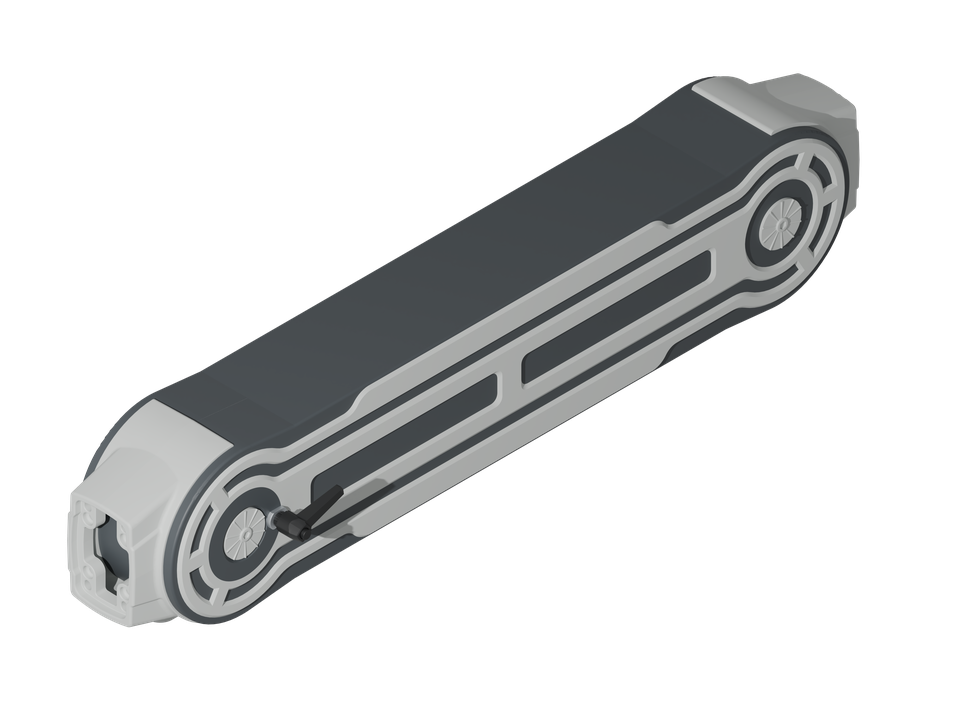
HIGHT ADJUSTABLE SOLUTION
Height Adjustable Support Arm
- Material
- Cast aluminum
- Colour
- RAL 7035
- Package Dimensions
- 185 × 870 × 430 mm
- HS Code
- 7606.99.90.19
- Warranty
- 5 years
Technical data
Specifications for planning, selection and use at a glance.
Material & finish
- Material Composition
- Cast aluminum
- RAL colours
- RAL 7035
Application & function
- Primary Use Case
- Machine Building / Automation / HMI operator stations
- Operating Temperature
- –40°C to +70°C
- Rated Voltage
- Mechanical (not subject to electrical certification)
Safety & compliance
- Earthing
- Yes, integrated solution
- RoHS Compliance
- RoHS EU Directive 2011/65/EU
- REACH Compliance
- REACH Regulation 1907/2006/EC
- Certification
- IEC 60529; (EG) No. 765/2008; (EU) 2023/956
Further information
- Protection Rating
- IP54
- Height adjustable
- Yes
- Bellows material
- Plastic
- Load range
- 4–30 kg
- Height adjustment range
- -300–300 mm
- Package weight
- 12.8 kg
- Maximum cable entry
- 20 × 60 mm
- Maximum connector size
- 34 × 15 mm
- Fasteners included
- Yes
- Assembly examples: shown limits
- L ≤ 500 mm; W ≤ 500 mm
Version & enquiry
Use the item number and version to prepare your enquiry.
| Choose a version | |
|---|---|
| SKU: X-M-HV01 |
SKU: X-M-HV01
Assembly instructions
About these instructions
Assembly sequence prepared from the exact XINDUX article data sheet. Tightening torques not specified in the source document are deliberately not added.
Preparation & tools
Required tools
- Allen key suitable for the fasteners
- Torque wrench for the final engineering check
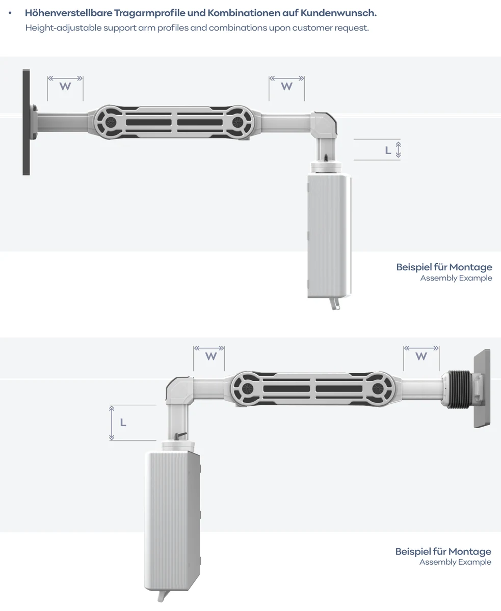
1. Prepare the components
Select mounting arrangement based on the permitted examples. The dimensions L and W may each be a maximum of 500 mm.
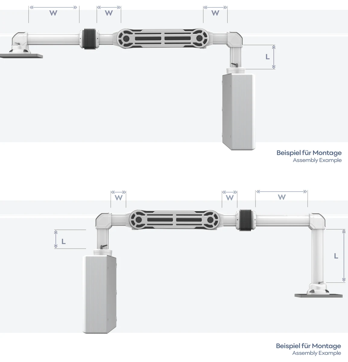
2. Prepare the components
Only plan two-part and multi-part arrangements within the L and W boundaries shown.
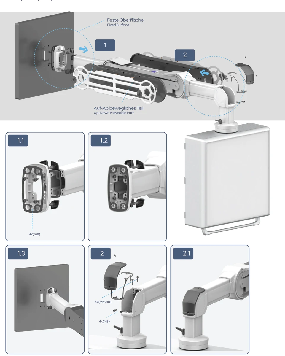
3. Fasten the connection
Assemble the solid surface, parts that move up and down, and covers according to the numbered sequence of images.
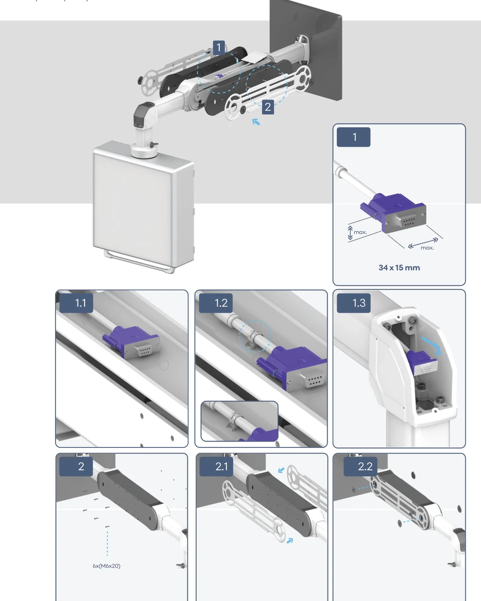
4. Install the cable guide
Lay cables and connectors up to a maximum of 34 × 15 mm through the cable guide provided and close the covers in the order shown.
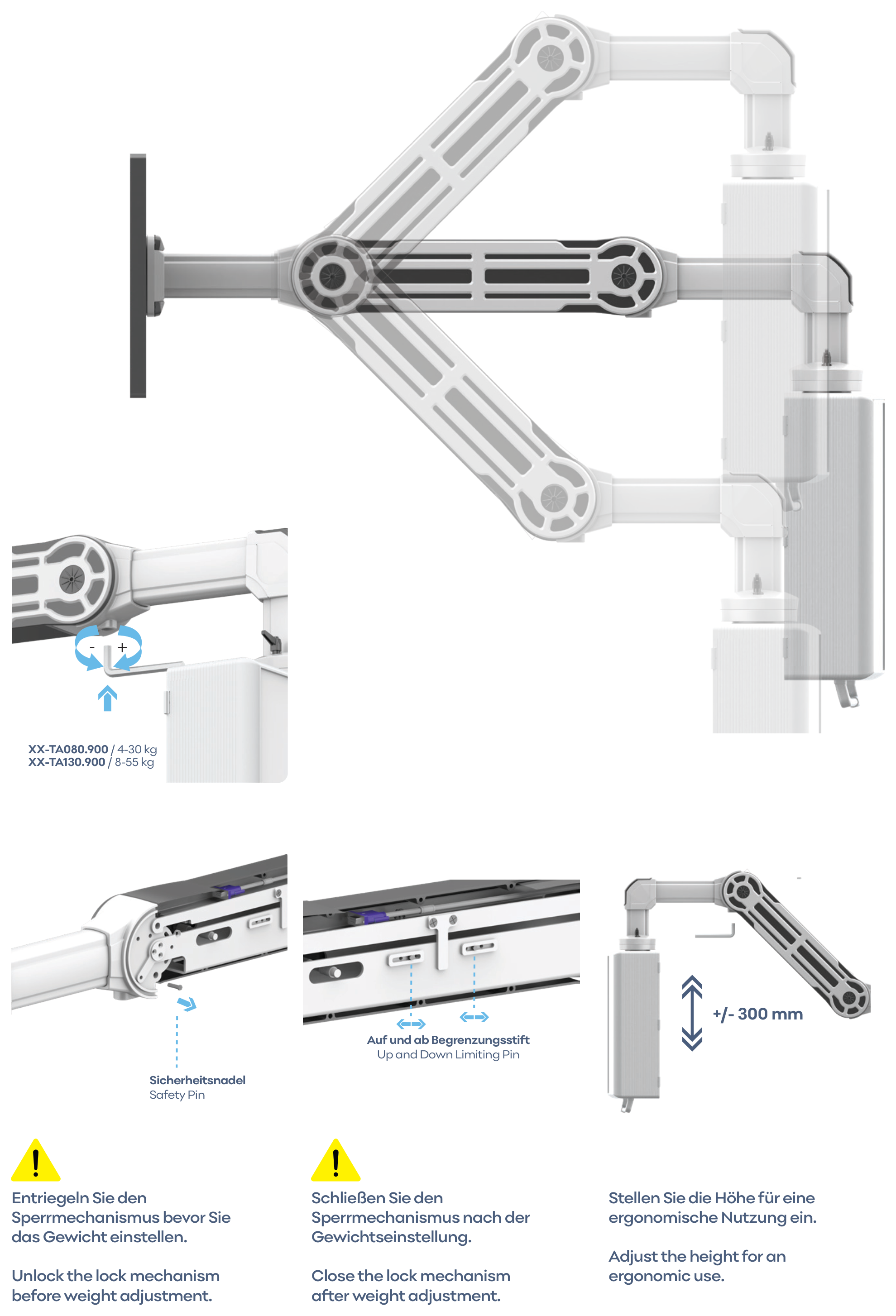
5. Align the system
Open the locking mechanism, adjust the load capacity, check the safety pin and limit pins, set the desired height within the adjustment range of ±300 mm and close the locking mechanism again.
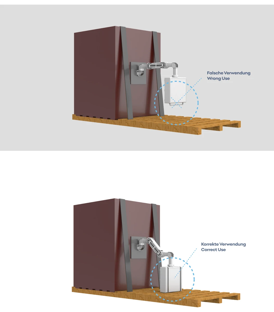
6. Transport safely
Do not use the transport position marked as incorrect.
For transport, support the system securely on the pallet in the position marked as correct. Do not use the transport position marked as incorrect.
Select a step or use the arrows. On mobile, swipe left or right.
Products in this series
 Panel Tilting Adaptor
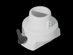 Ø48 Adaptor
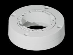 Rotatable Panel Coupling
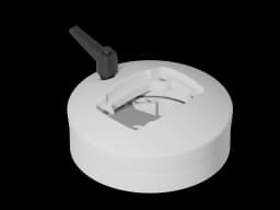 Rotatable Panel Coupling
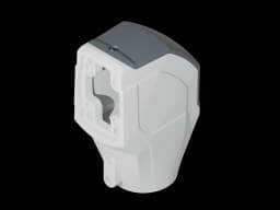 080/Ø48 Adaptor
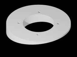 Ø134 mm 10° Panel Adaptor
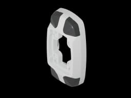 Wall-Socket Mounting Bracket
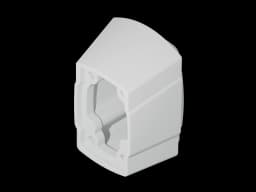 080 / 050 Support Arm Adaptor
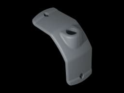 Warning Lamp Cover (M22)
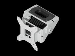 Vesa Panel Tilting Adaptor Moving
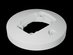 Panel Coupling
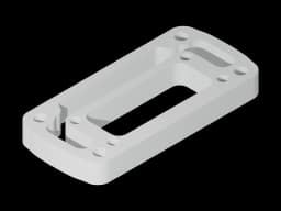 080 Panel Adaptor
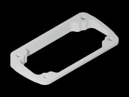 10° Angle Piece
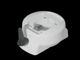 Rotatable Panel Adaptor Vertical
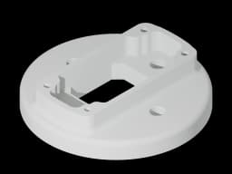 Ø134 mm Panel Adaptor
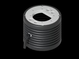 Ø130 mm Panel Tilting Adaptor - With Bellows
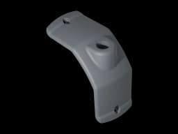 Warning Lamp Cover (M18)
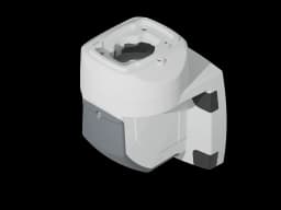 Rotatable Wall-Mounted Hinge Vertical Outlet
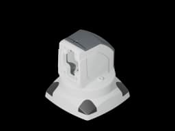 Rotatable Top Mounted 90° Angle Joint
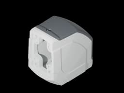 90° Angle Piece
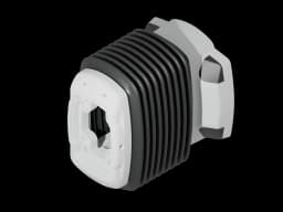 Steel Wall Mounted Module - With Bellows
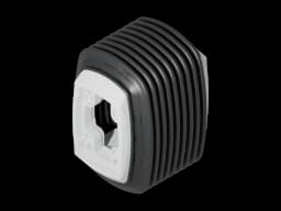 Steel Interconnection Module - With Bellows
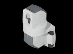 Rotatable Wall-Mounted Hinge Horizontal Outlet
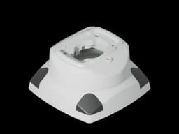 Rotatable Top Mounted Vertical Outlet
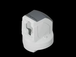 Rotatable Panel 90° Angle Coupling
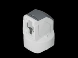 Rotatable profile joint
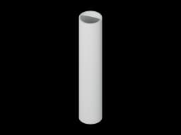 Ø48 Pipe Profile
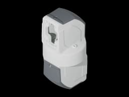 Rotatable Intermediate Hinge
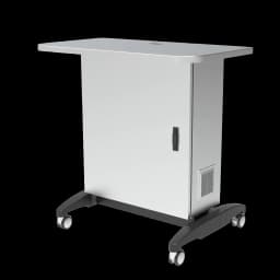 Mobile HMI PC cabinet station
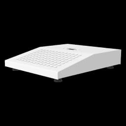 HMI base
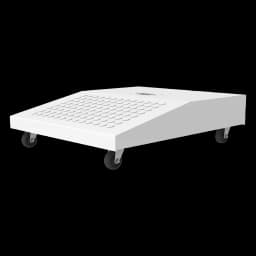 mobile kiosk base with castors
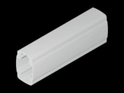 080 Support Profile - 1000mm · X-M