
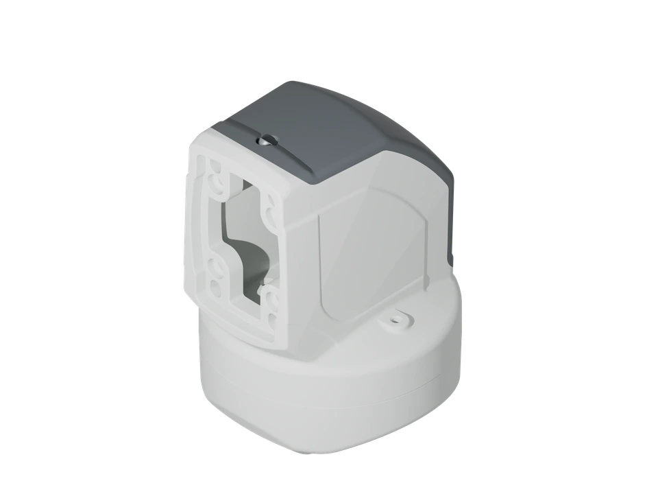
ADAPTORS / JOINT PARTS
Rotatable profile joint
- Series
- LARGO
- Type
- rotatable
Technical data
Specifications for planning, selection and use at a glance.
Further information
- Series
- LARGO
- Type
- rotatable
- Calculated carton external dimensions (X × Y × Z)
- 187.80 × 246.99 × 190.14 mm
- Calculated carton internal dimensions (X × Y × Z)
- 177.80 × 236.99 × 180.14 mm
- CAD envelope dimensions (X × Y × Z)
- 167.80 × 226.99 × 170.14 mm
Version & enquiry
Use the item number and version to prepare your enquiry.
| Choose a version | |
|---|---|
| SKU: X-L-PWK03 |
SKU: X-L-PWK03
Assembly instructions
About these instructions
Internal source draft. This is not a new manufacturer engineering approval. Clarify unresolved fastener and quantity questions before assembly.
The source does not specify tightening torques. Confirm connection-specific values before assembly; secure the assembly and support the load.
The R01 draft places original steps 11–14 before original step 1. All 18 original steps and their locations are retained. This reordered sequence is inherited editorial organization, not new engineering approval.
No verified supplied-kit list or protective-earth evidence is established. The earlier operator statement about the ball remains internally documented.
The illustrations retain original captions and original numbering. Conflicting statements are identified in the warnings. Read the DE/EN instructions separately from the Turkish/English image content.
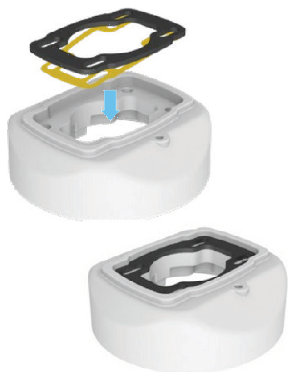
1. Fit the gasket
Lower profile connection: Remove the protective film. Fit the illustrated gasket with its adhesive side against the corresponding seat. Check that it is seated all around.
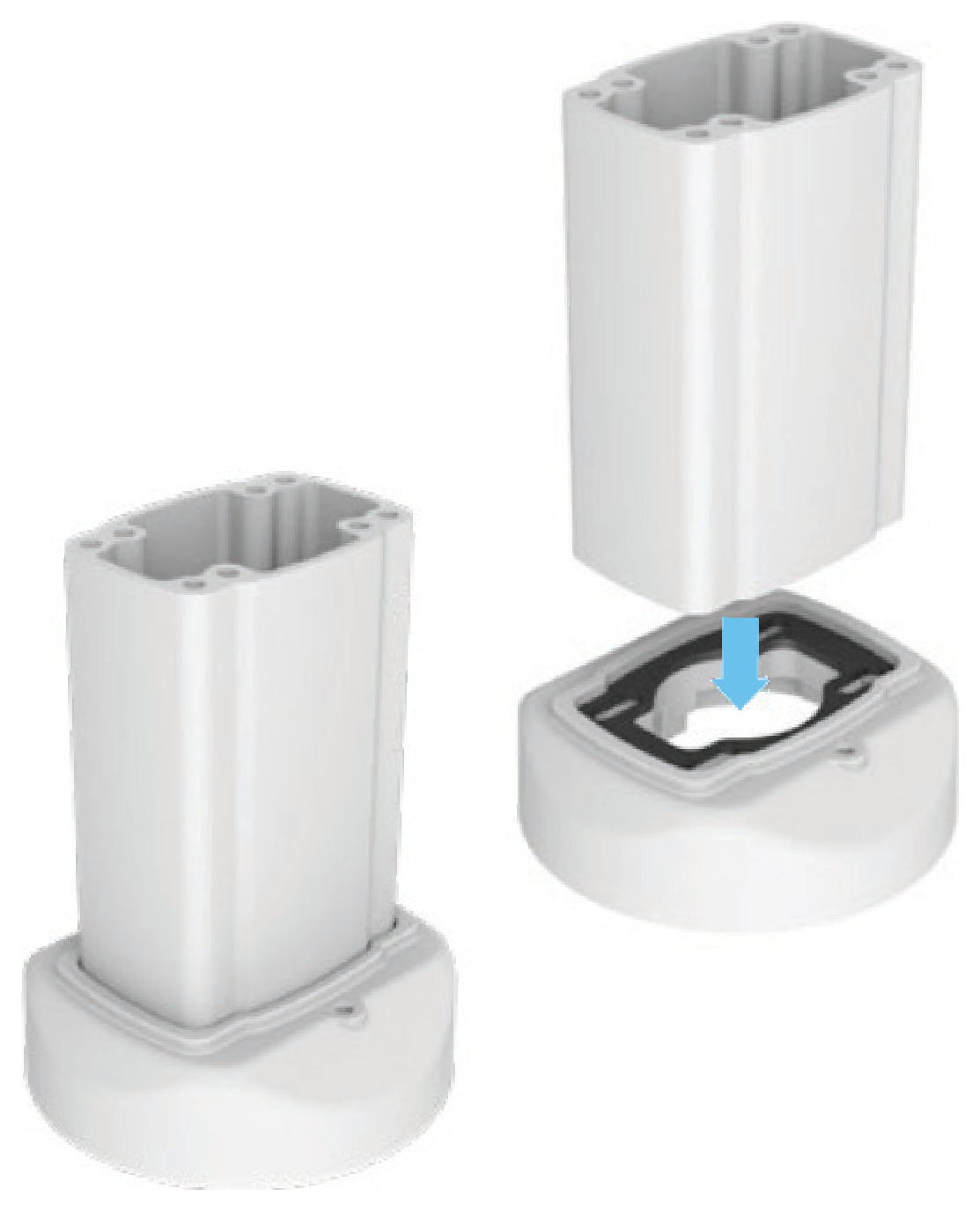
2. Insert the profile
Insert the lower profile into the sealed connection. Complete this preparation before closing the rotary bearing unit.
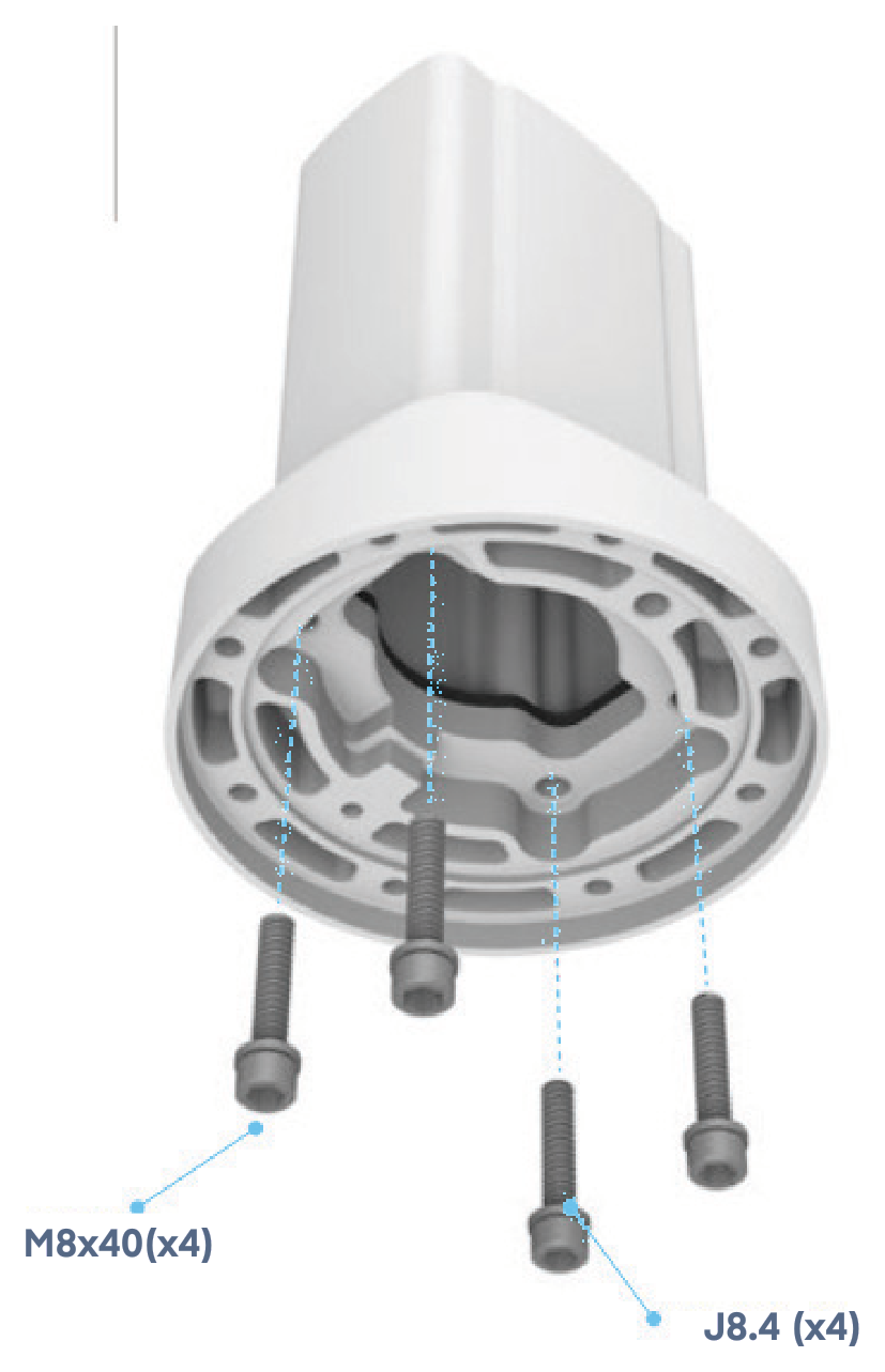
3. Fasten the connection
Fasten the lower profile using four M8 × 40 bolts and four J8.4 washers.
- 4 × M8 × 40
- 4 × J8.4
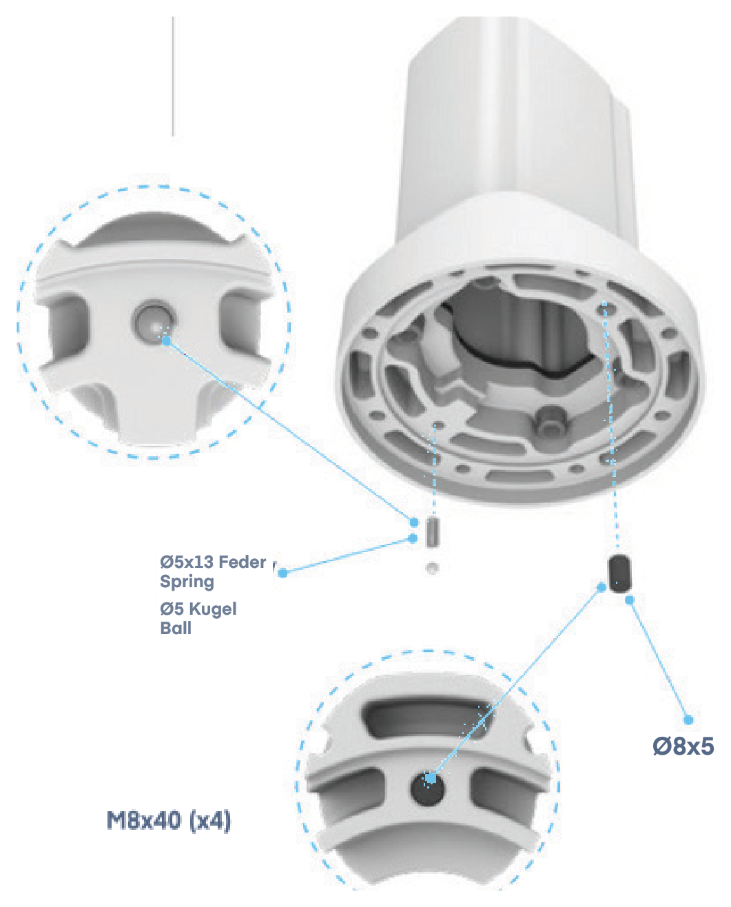
4. Insert ball, spring and brake piece
Insert the ball, spring and plastic brake piece into their illustrated seats before closing the rotary bearing. Check orientation and complete seating.
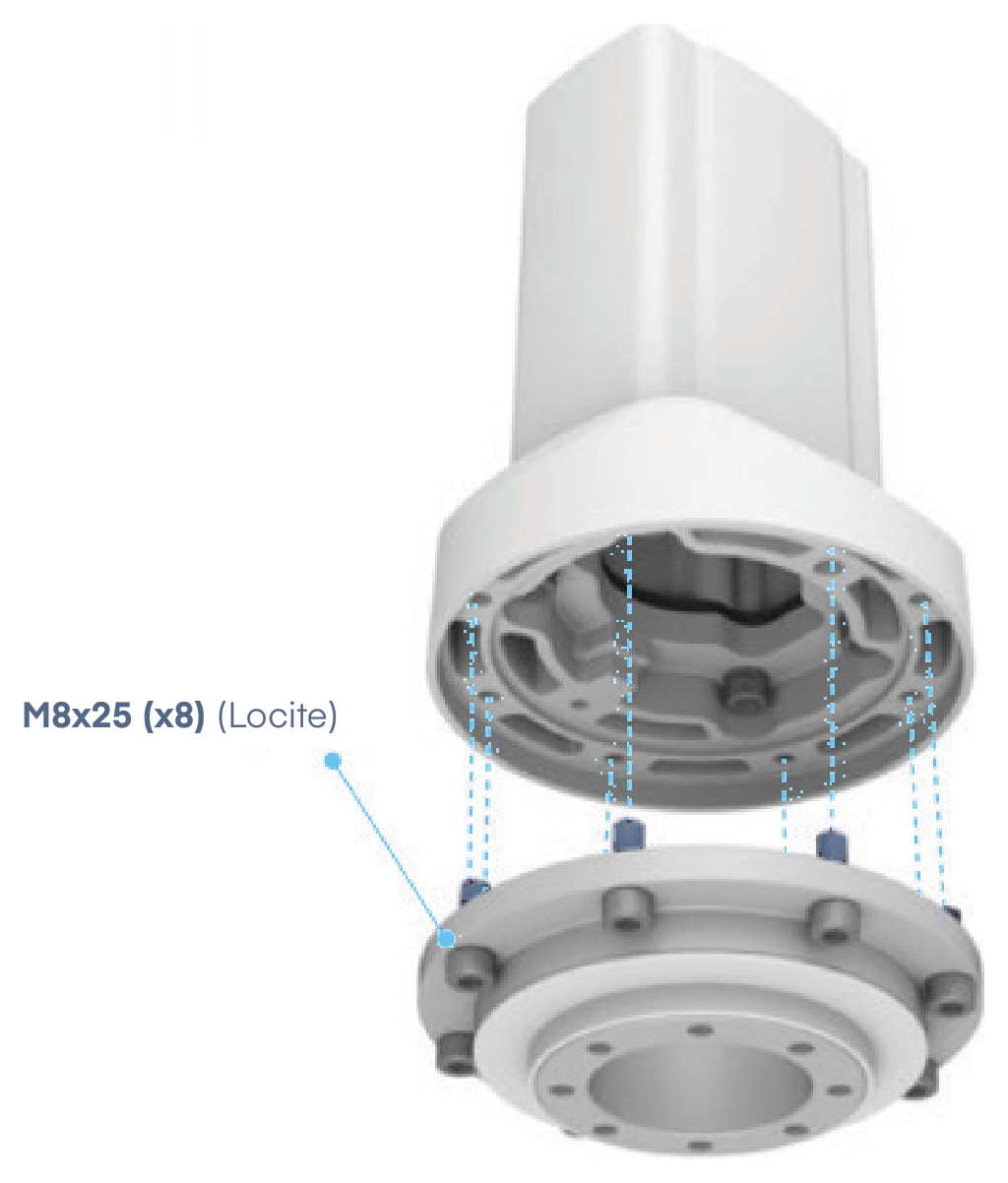
5. Fasten the connection
Connect the prepared lower unit to the rotary bearing using eight M8 × 25 bolts. The source marks these bolts as threadlocked.
- 8 × M8 × 25 · threadlocking indicated by source
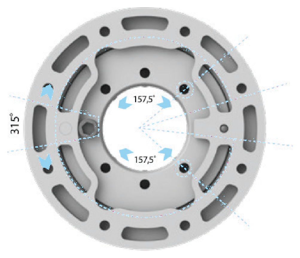
6. Set the rotation stops
The source text specifies M8 × 10, but these bolts are absent from the parts overview. Confirm the stop fasteners before assembly; do not select substitutes by thread diameter alone.
The source shows eight possible stop positions and a total range of 315°. Two stops define the end positions.
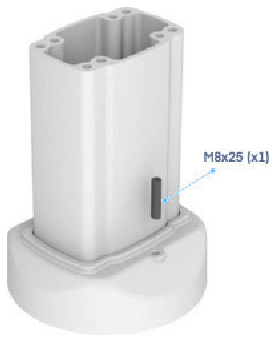
7. Adjust the mechanism
The plastic brake piece and set screw belong in the same seat. Fit the M8 × 25 set screw as illustrated.
- 1 × M8 × 25
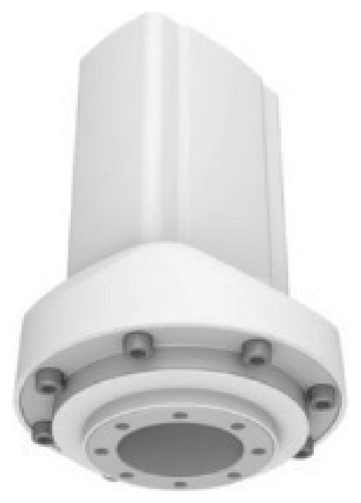
8. Inspect the assembly
Compare the assembled unit with the illustration. Check that the components and connections are correctly seated.
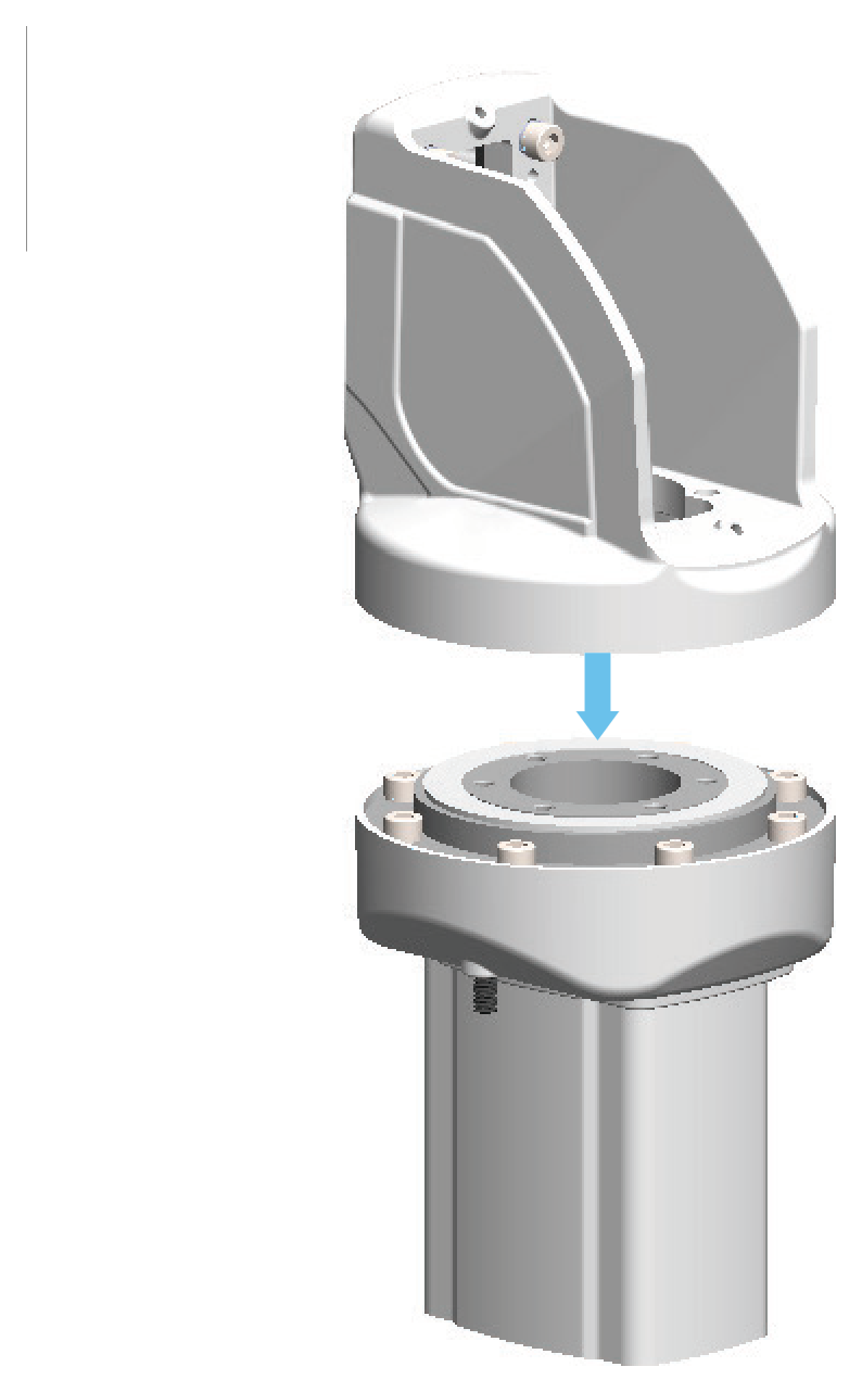
9. Prepare the assembly
Bring the upper part together with the prepared lower unit. The final connection is shown in the later fastening step.
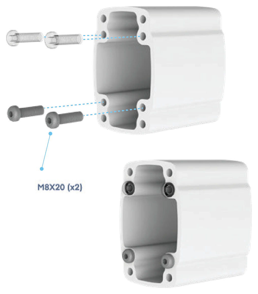
10. Adjust the mechanism
The parts overview lists four M8 × 20 angle-adjustment bolts; original steps 6 and 8 each show two. Confirm the allocation before assembly. Repeated illustrations do not automatically establish additional fasteners.
Insert the two illustrated M8 × 20 angle-adjustment bolts into their seats.
- 2 × M8 × 20
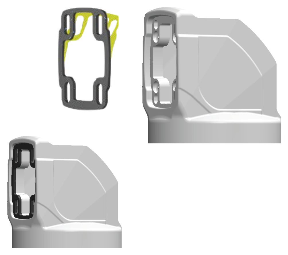
11. Fit the gasket
Horizontal profile connection: Remove the protective film. Fit the illustrated gasket with its adhesive side against the corresponding seat. Check that it is seated all around.
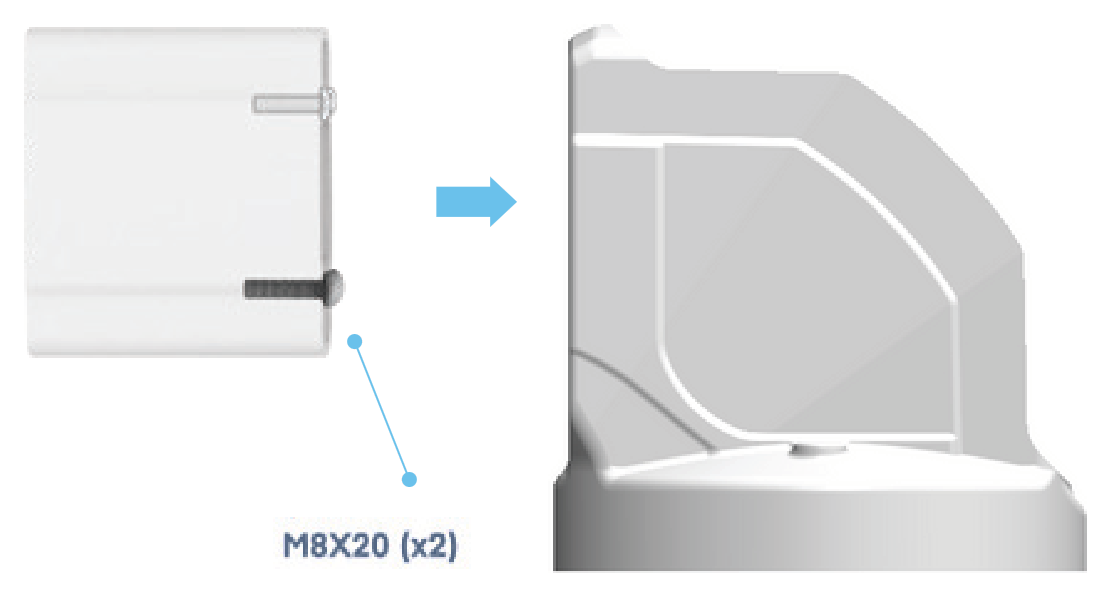
12. Insert the profile
Insert the horizontal profile into the connection. The angle-adjustment bolts remain in the positions illustrated.
- 2 × M8 × 20
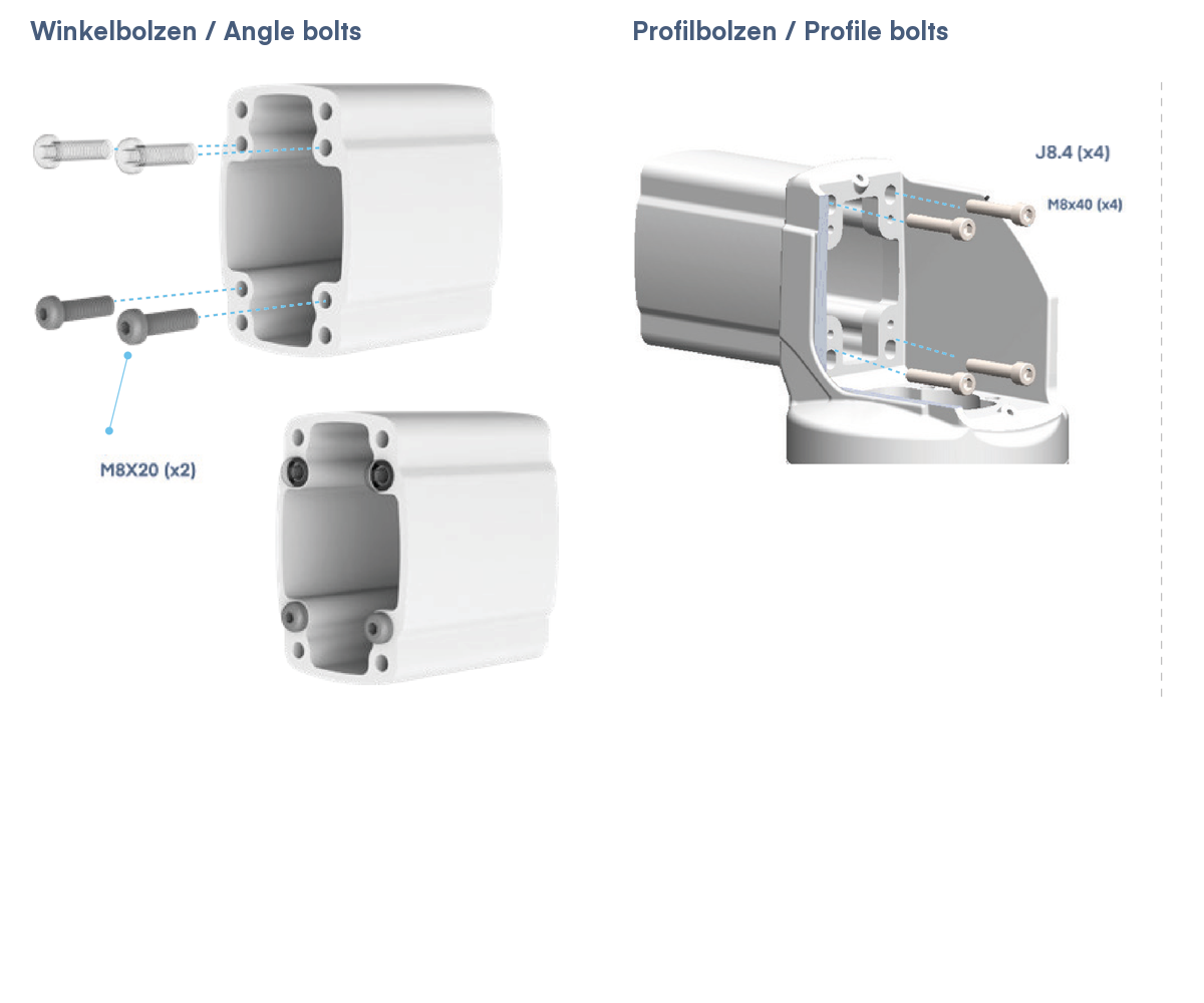
13. Adjust the mechanism
The Turkish and English original passages specify M6 × 20/M6 × 30; the English text also mixes up bolt roles. Article-specific drawings 6 and 8 show M8 × 20 for angle adjustment, and drawing 10 shows M8 × 40 for profile fastening. This draft follows those drawings; resolve the source discrepancy before assembly.
If there is no sagging, leave the angle-adjustment bolts in their initial position. For correction, loosen the M8 × 40 profile bolts by 2–3 mm as stated in the source, align the supported profile with the M8 × 20 angle-adjustment bolts, then retighten the profile bolts. Check the inclination with a spirit level.
- M8 × 40 · profile
- M8 × 20 · angle adjustment
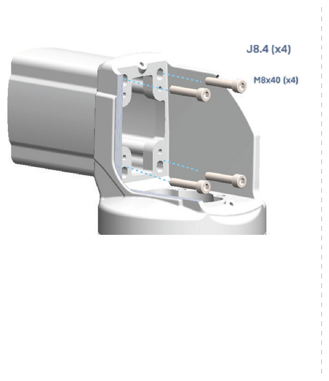
14. Fasten the connection
Fasten the horizontal profile using four M8 × 40 bolts and four J8.4 washers.
- 4 × M8 × 40
- 4 × J8.4
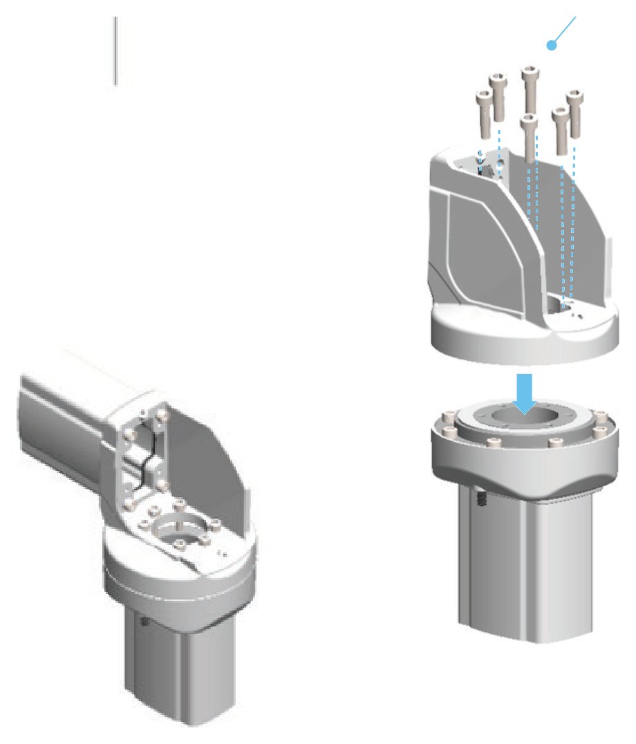
15. Fasten the connection
The step label says ×1, the drawing shows multiple bolts and the parts overview lists six. Confirm the required quantity before assembly.
Connect the upper part and lower unit in the illustrated position. The source specifies M8 × 40 for this connection.
- M8 × 40 · quantity to be confirmed before assembly
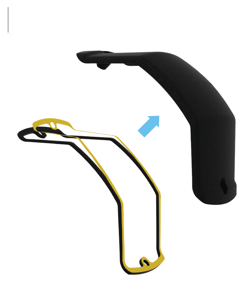
16. Fit the gasket
Cover gasket: Remove the protective film. Fit the illustrated gasket with its adhesive side against the corresponding seat. Check that it is seated all around.
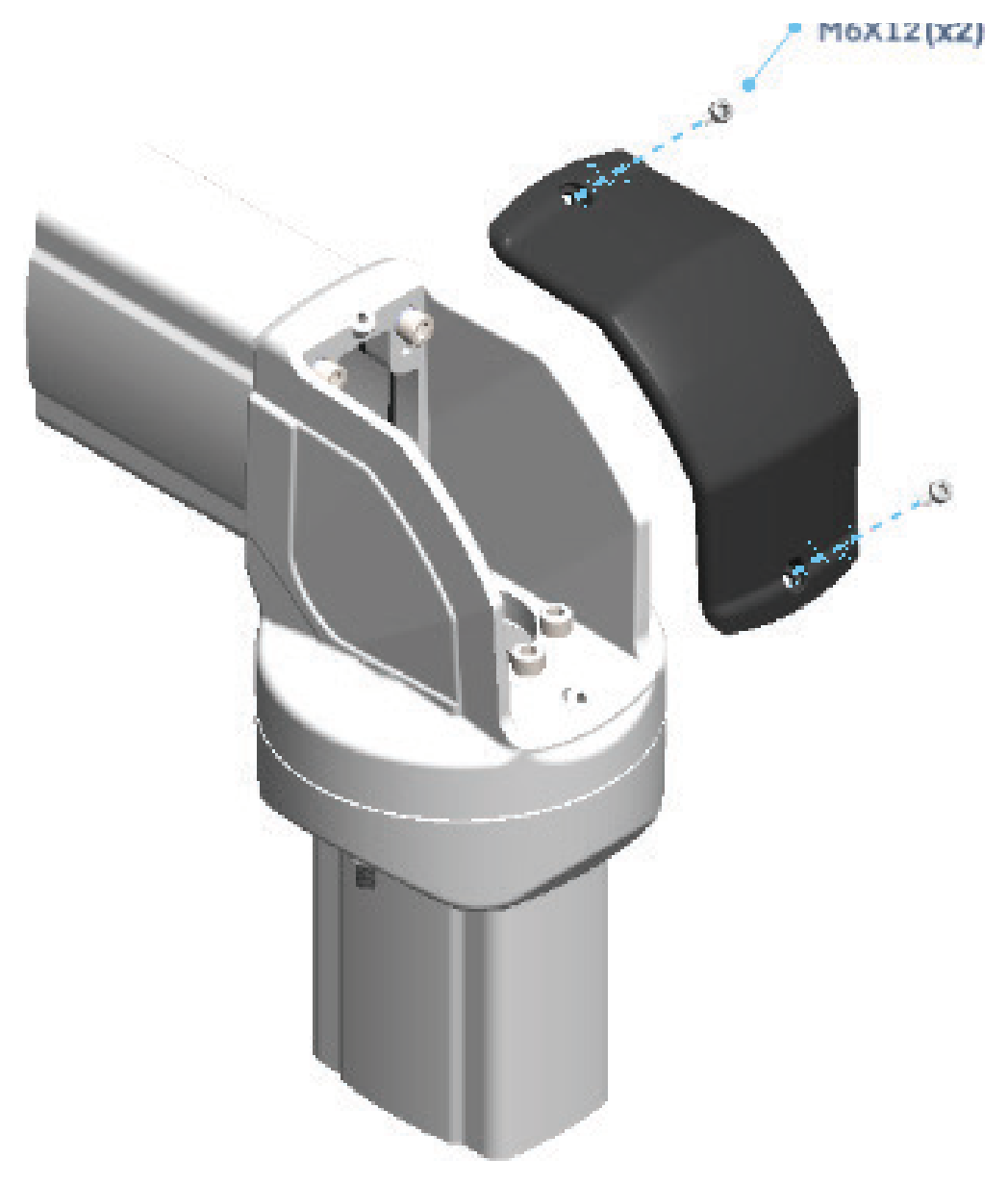
17. Fit the cover
The cover screws are not clearly listed separately in the parts overview. Check them against the supplied kit before assembly.
Position the cover as illustrated. The mounting step identifies the two cover screws as M6 × 12.
- 2 × M6 × 12 · as labelled in assembly step
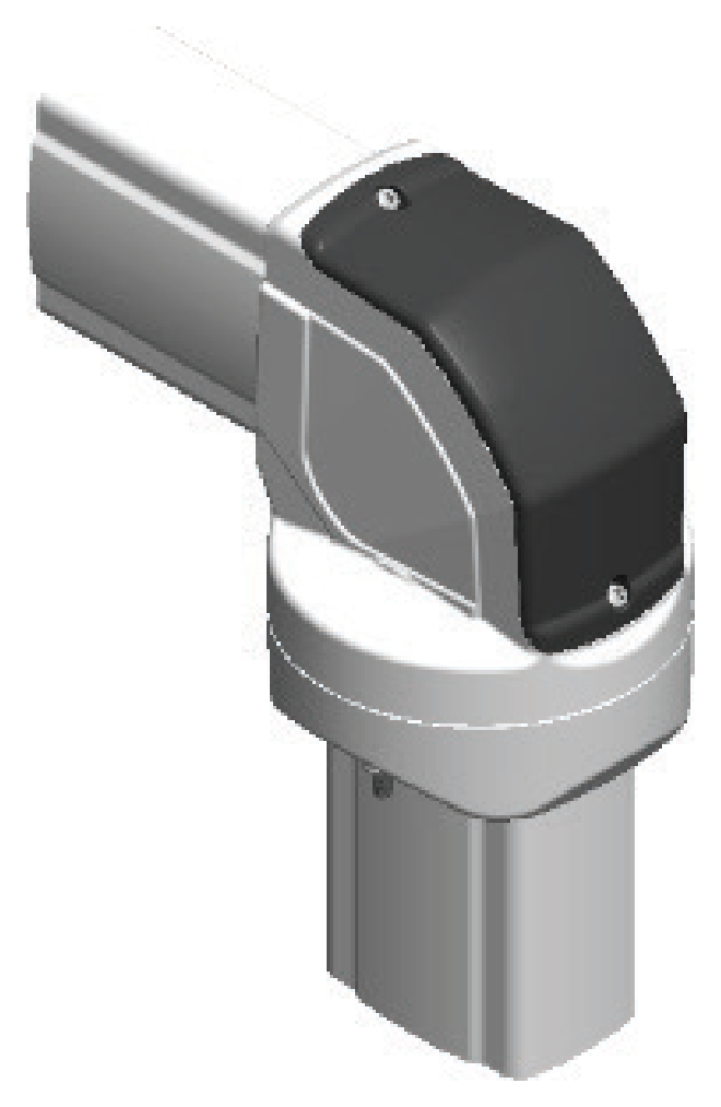
18. Inspect the assembly
Check the cover and gaskets. Correct any trapped or displaced gasket before commissioning.
Select a step or use the arrows. On mobile, swipe left or right.
Products in this series
 Warning Lamp Cover (M22)
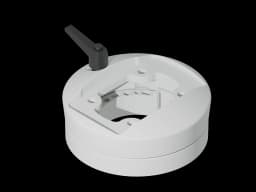 Rotatable Panel Coupling
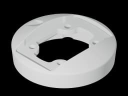 Panel Coupling
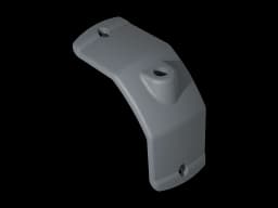 Warning Lamp Cover (M18)
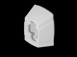 130/080 Support Arm Adaptor
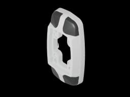 Wall-Socket Mounting Bracket
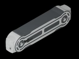 Height Adjustable Support Arm
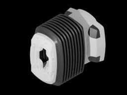 Steel Wall Mounted Module - With Bellows
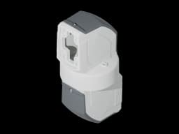 Rotatable Intermediate Hinge
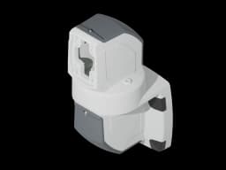 Rotatable Wall-Mounted Hinge Horizontal Outlet
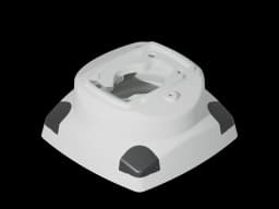 Rotatable Top Mounted Vertical Outlet
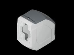 90° Angle Piece
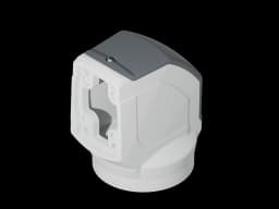 Rotatable Panel 90° Angle Coupling
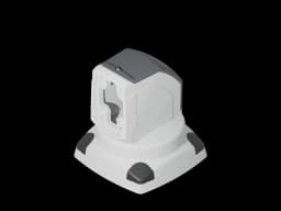 Rotatable Top Mounted 90° Angle Joint
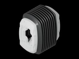 Steel Interconnection Module - With Bellows
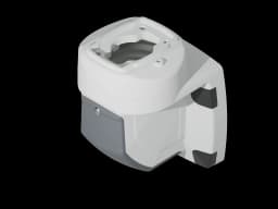 Rotatable Wall-Mounted Hinge Vertical Outlet
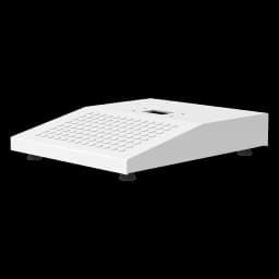 kiosk base with levelling feet
 kiosk base with flange
 mobile kiosk base with castors
 130 Support Profile - 1000mm · X-L