
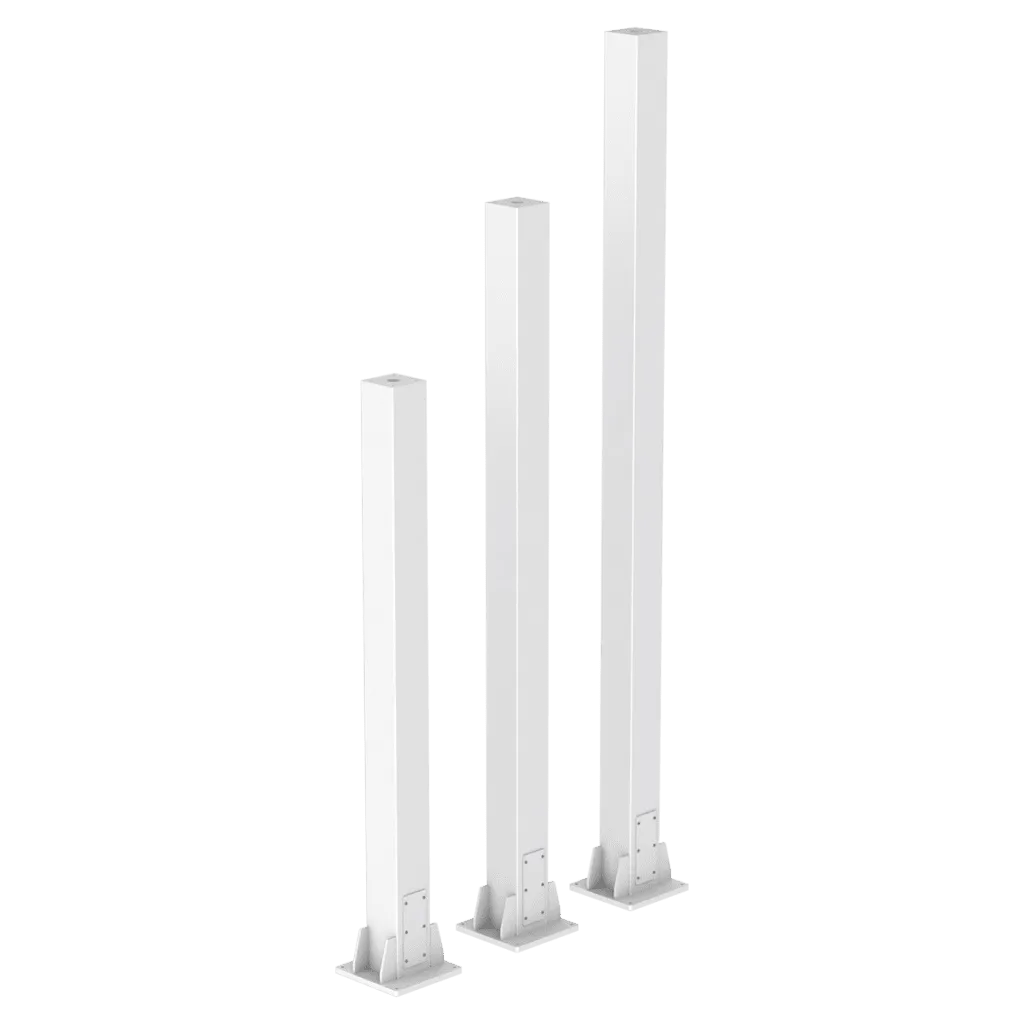
Kiosk systems
Stand tower
- Material Composition
- Aluminum 6000
- Colour
- 7035
- HS Code
- 7606.99.90.19
- Warranty
- 5 years
Technical data
Specifications for planning, selection and use at a glance.
Material & finish
- Material Composition
- Aluminum 6000
- Colour
- 7035
Application & function
- Primary Use Case
- Machine Building / Automation / HMI operator stations
- Operating Temperature
- –40°C to +70°C
- Protection Rating
- –IP65 (DIN EN 60529)
- Rated Voltage
- Mechanical (not subject to electrical certification)
Safety & compliance
- Earthing
- Yes, integrated solution
- RoHS Compliance
- RoHS EU Directive 2011/65/EU
- REACH Compliance
- REACH Regulation 1907/2006/EC
- Certification
- IEC 60529; (EG) No. 765/2008; (EU) 2023/956
Version & enquiry
Use the item number and version to prepare your enquiry.
| Choose a version | |
|---|---|
| Stand towerSKU: X-ST-TW01 |
Stand towerSKU: X-ST-TW01
Assembly guide
About these instructions
Dimension drawings for types 150 and 200. CAD reference: type 200 with 3,000 mm overall height.
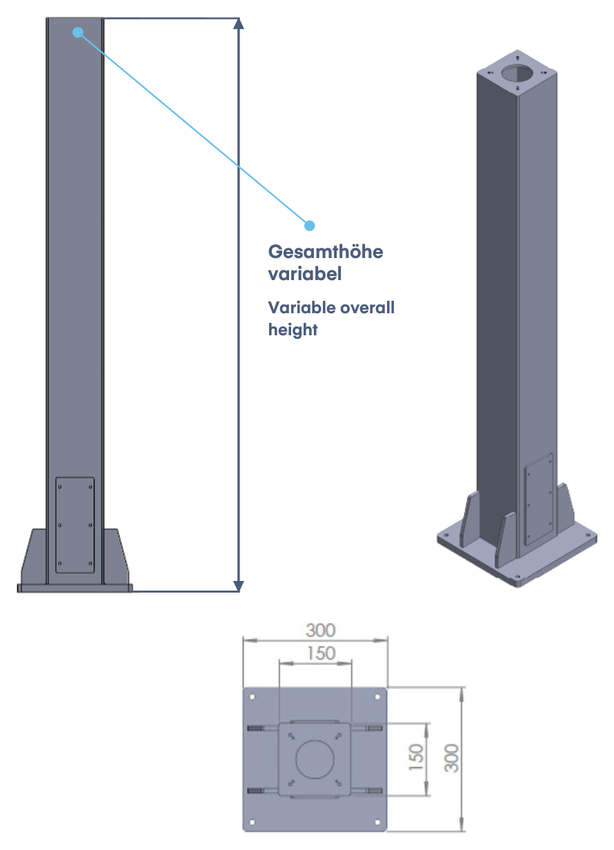
1. Type 150: overall dimensions
The drawing shows a 150 x 150 mm column section and a 300 x 300 mm base plate. The overall height is specified for the individual project.
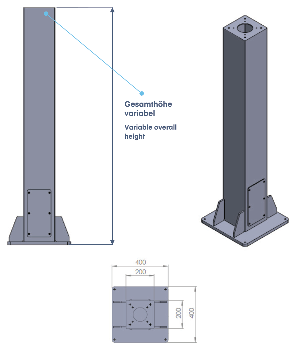
2. Type 200: overall dimensions
The drawing shows a 200 x 200 mm column section and a 400 x 400 mm base plate. The separate CAD example represents this type with an overall height of 3,000 mm.
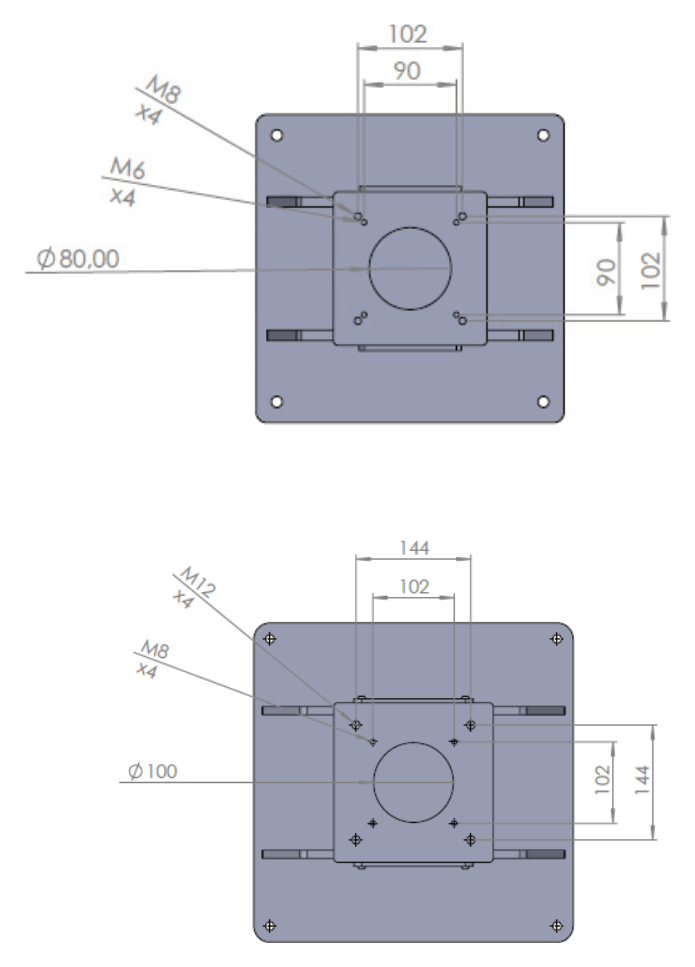
3. Define the upper support-arm interface
These drawings are interface examples. They do not establish general interchangeability between support-arm groups.
The upper connection plate is adapted to the support-arm group used. The drawing shows two connection patterns. Confirm the pattern for the intended assembly before installation.
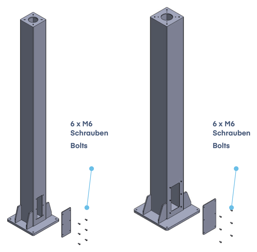
4. Access for cable routing
The sheet-metal side cover provides access to the cable route inside the tower. The illustration shows the cover removed and six M6 bolts per tower. The connection-element overview specifies M6 x 16.
- 6 x M6, Übersicht / overview: M6 x 16
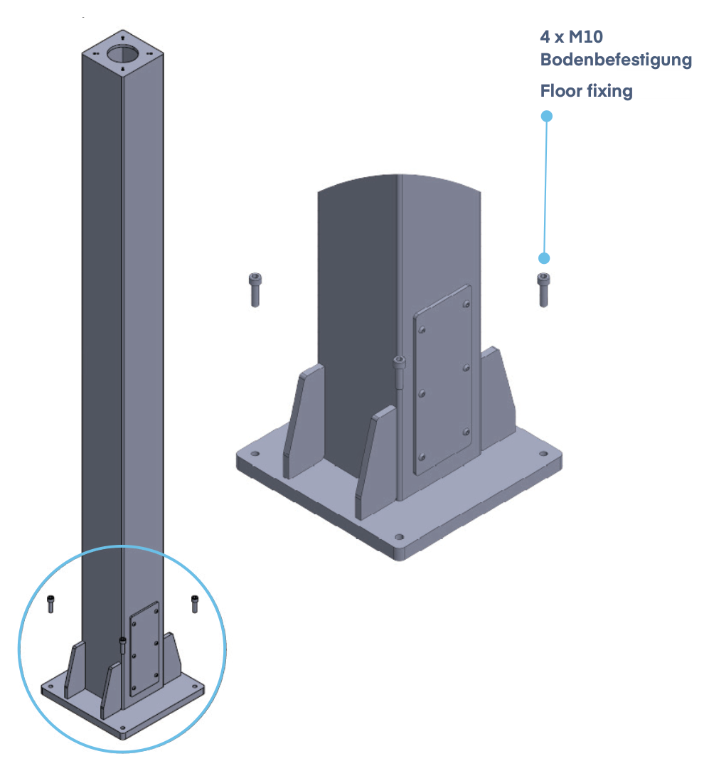
5. Fix the tower to the floor
The source does not specify floor anchors or tightening torques. M10 x 16 is not a general floor-anchor specification.
The drawing shows four M10 fixing positions on the base plate. The connection-element overview specifies M10 x 16. The floor fixing must suit the substrate and the individual assembly.
- 4 x M10, Übersicht / overview: M10 x 16
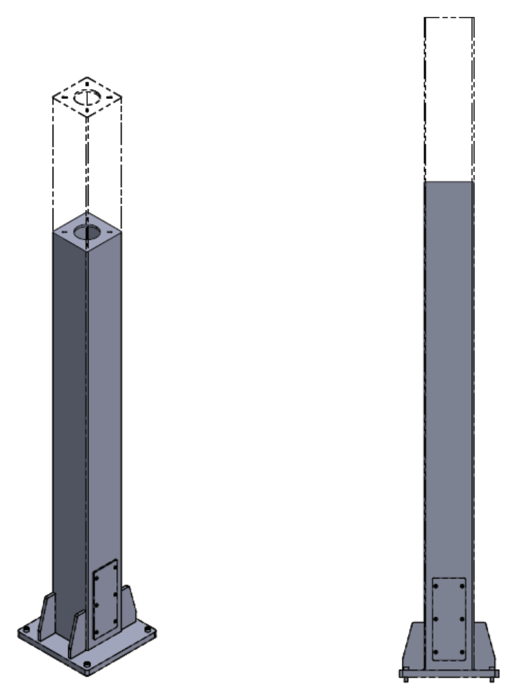
6. Specify the overall height
This illustration describes overall-height specification. It does not establish height adjustment during operation.
Types 150 and 200 can be supplied with project-specific overall heights. The dashed outlines illustrate this variation. Agree the height before placing the order.
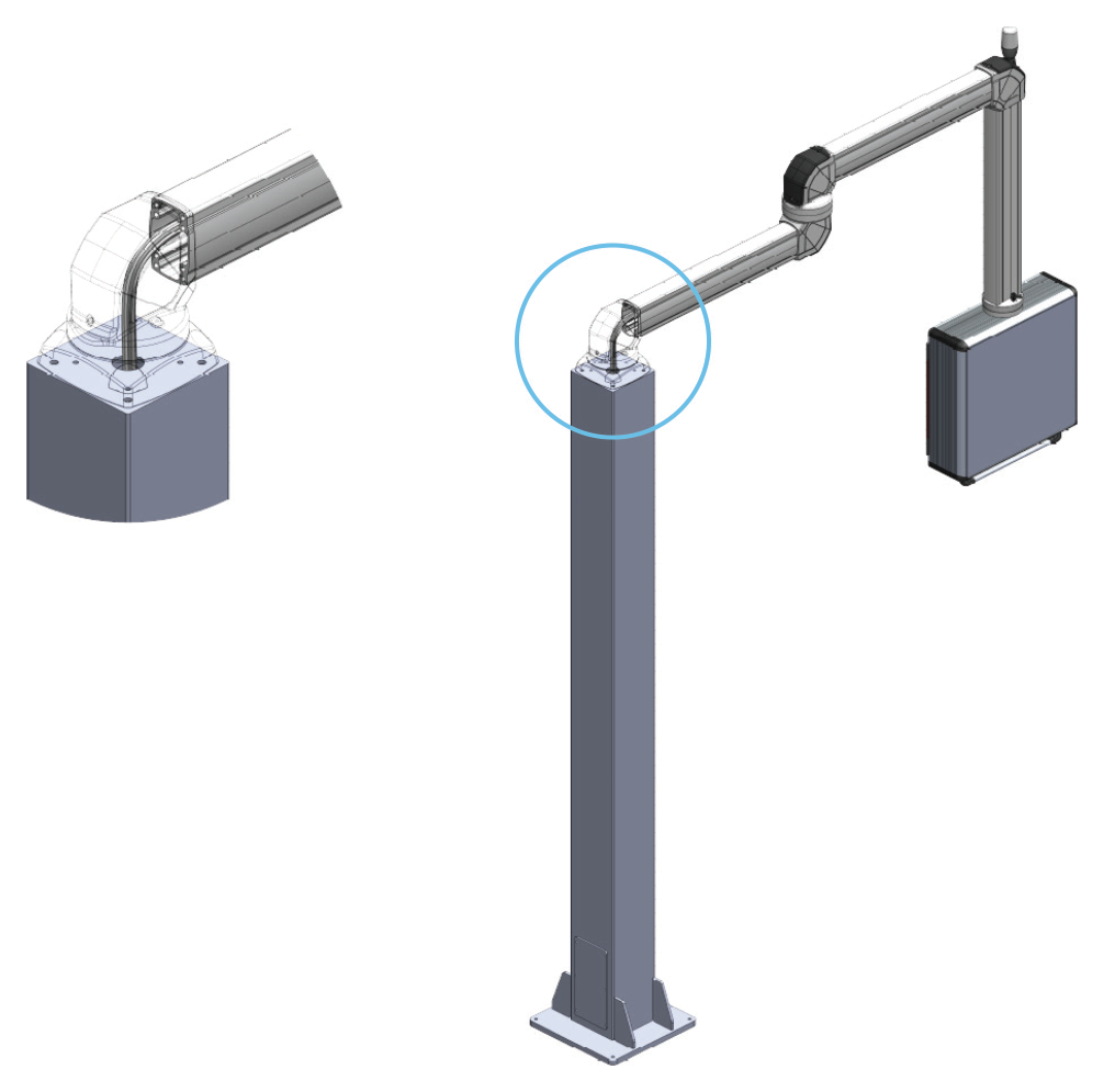
7. Route cables through tower and arm
Openings in the tower and support arm allow internal cable routing. The cover near the base provides access to the interior. Project-specific designs are agreed in advance.
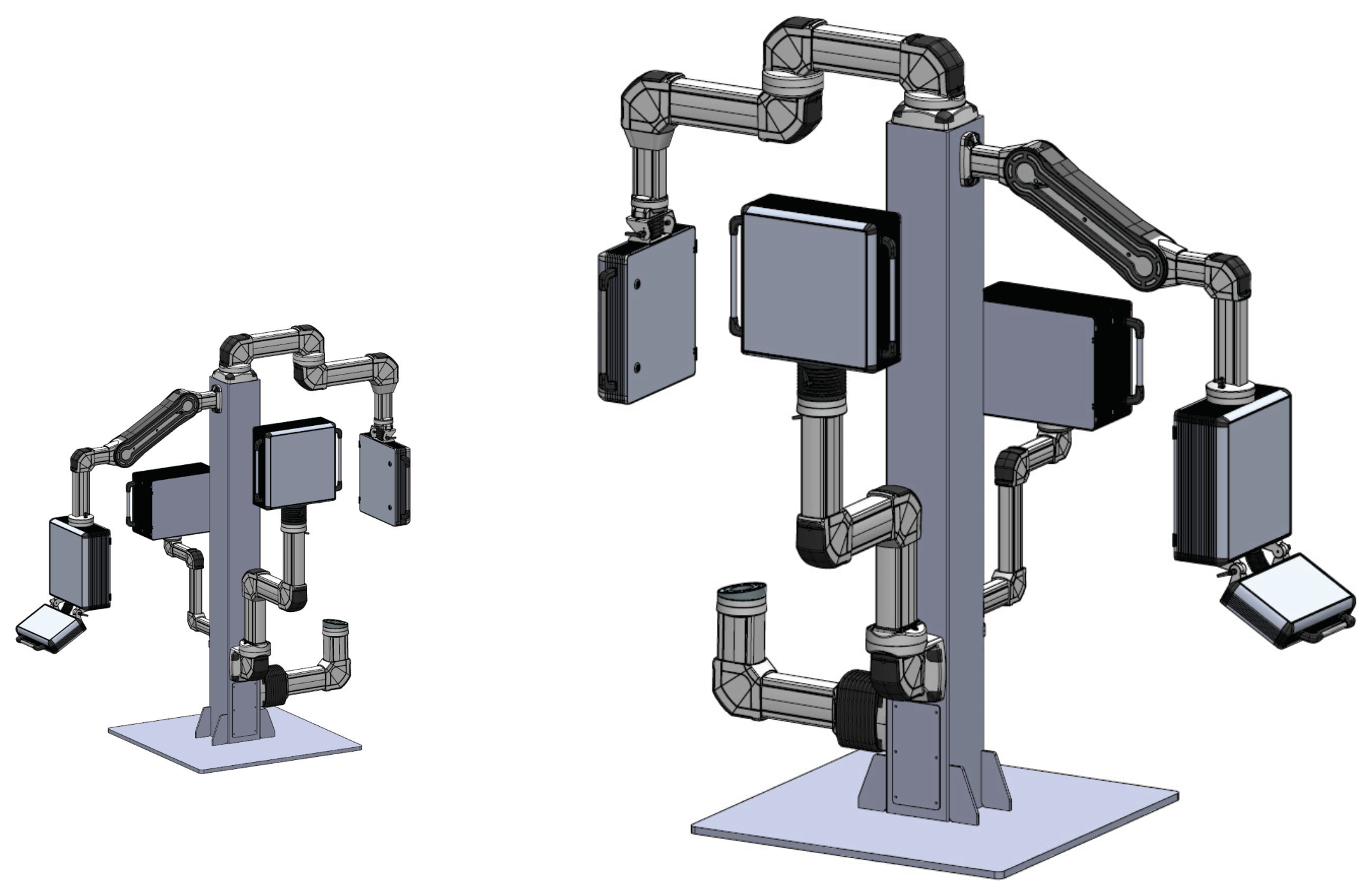
8. Examples with support arms
The images are application examples. Confirm the specific combination and loading for the individual assembly.
The illustrations show possible tower assemblies with support arms and operator devices. The connection plate, layout and cable route are defined for the selected support-arm group.
Select a step or use the arrows. On mobile, swipe left or right.
Frequently Asked Questions
Support arm systems are designed to safely mount and position HMI panels, operator interfaces,
keyboards, and control devices. They enable ergonomic operation, flexible movement, and stable
positioning in industrial environments.